


The KB Discomatic
This page includes facts and photos about the KB Discomatic, also a little speculation.
Who designed and built the KB Discomatic?
I have no records to confirm this, but popular belief is that both design and assembly of the KB Discomatic took place by KB in the UK, housing a player mechanism supplied to them by Gerinvex.
What evidence is there to prove this? Quite a lot. Whilst the mechanism and chassis comprise only metric fasteners, the cabinet and amplifier fasteners are imperial sizes. Also that the amplifier was a standard KB unit, used in KB record player models (ref. Mike Edwards, KB museum), and the speaker was made by ELAC in the UK. This does suggest to me that KB were responsible for the design and build of their Discomatic, perhaps to earn recognition as being 'made in Britain' if a high enough percentage of the parts were sourced in the UK.
How much of the KB Discomatic would have been UK sourced?
Most likely the cabinet and fittings, also the wiring, vents, lamps, amplifier and speaker whilst Gerinvex supplied the mechanism, record rack and dustcover.
I am suspicious however that this may not be the whole story. Check out these photos of early Discomatic adverts published by KB and Gerinvex. Both photos show a KB, but the Gerinvex version has no 'KB' legends on the front panel or title card.
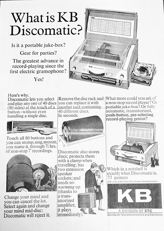
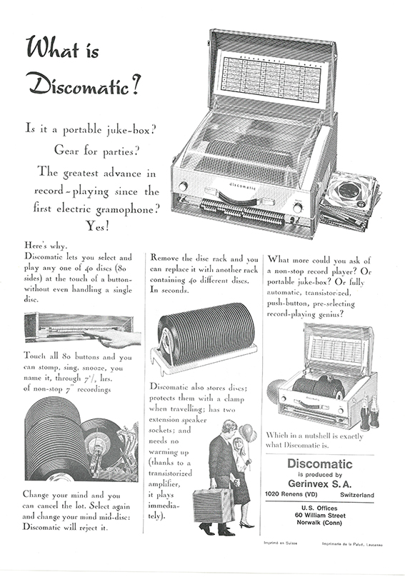
So what machine is this on the 'non-KB' advert? Did Gerinvex also sell a Discomatic identical to the KB? Or was the KB a Gerinvex design, sold to KB to manufacture in the UK? Perhaps they just needed a photo for their adverts and the KB was the only completed Discomatic design that they could photograph?
I do think this latter is the most likely explanation though it does make for interesting speculation. In my view the Gerinvex ad looks to be the original with the KB ad derived from it. Whatever the story, it is very likely that Gerinvex and KB were working closely together on the design of this player.
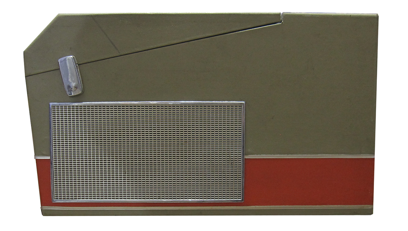
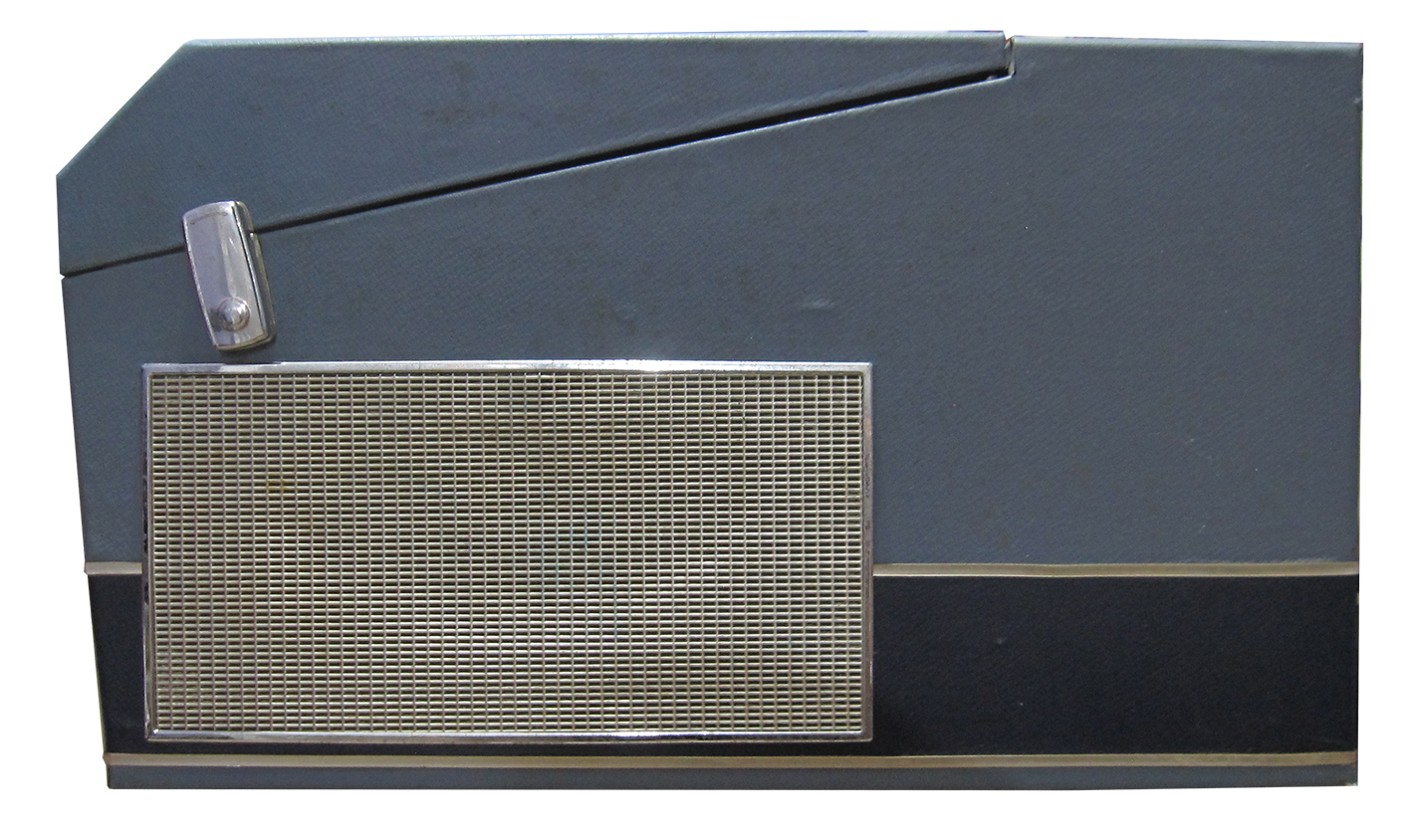
KB Discomatic colours
The KB Discomatic was available in two colours. Early models were available in two-tone grey/orange, for later models two-tone blue was added as an option. The KB dustcover was coloured with a light grey tint and the record rack was a cream colour.
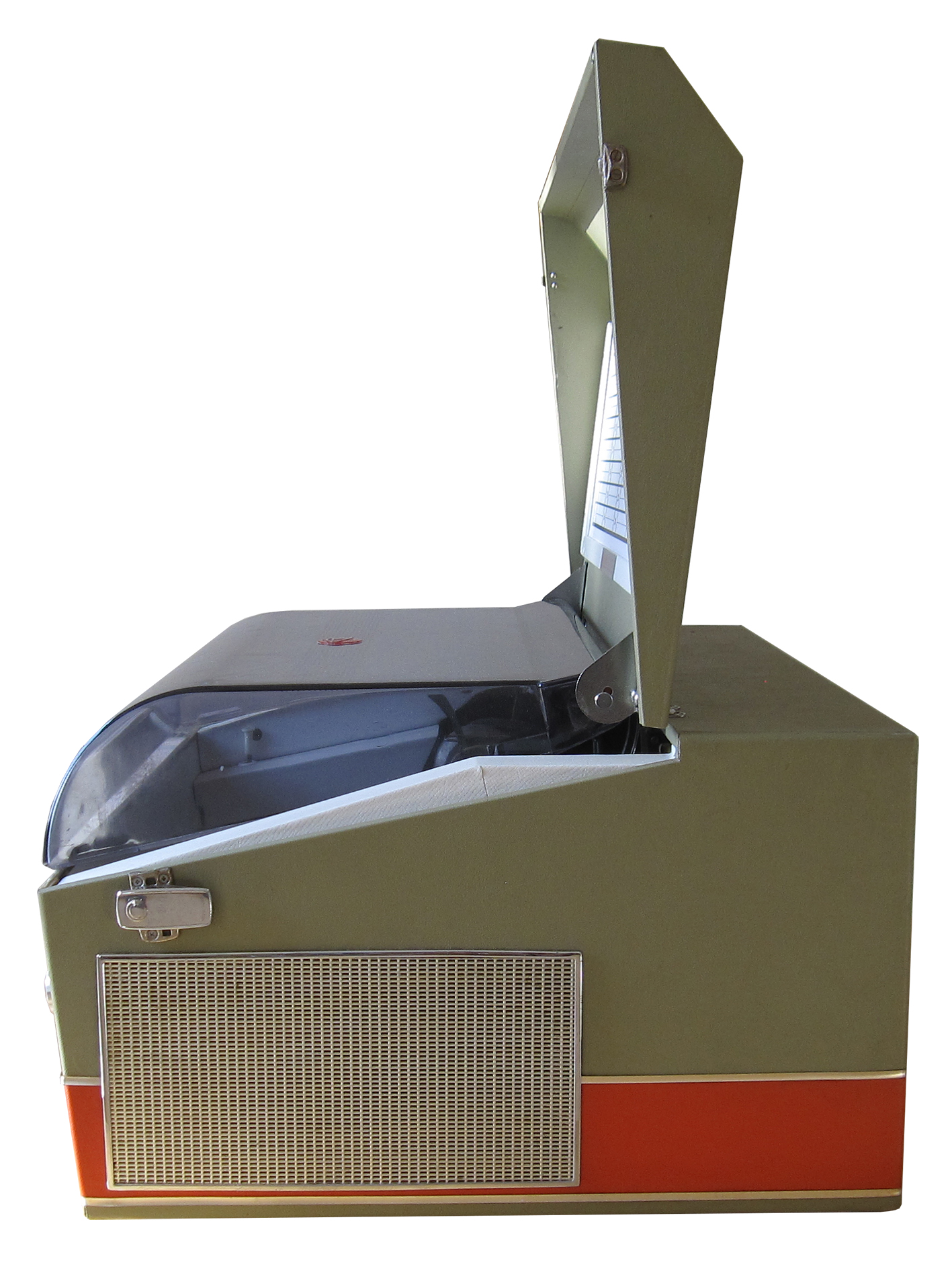
KB Discomatic lid
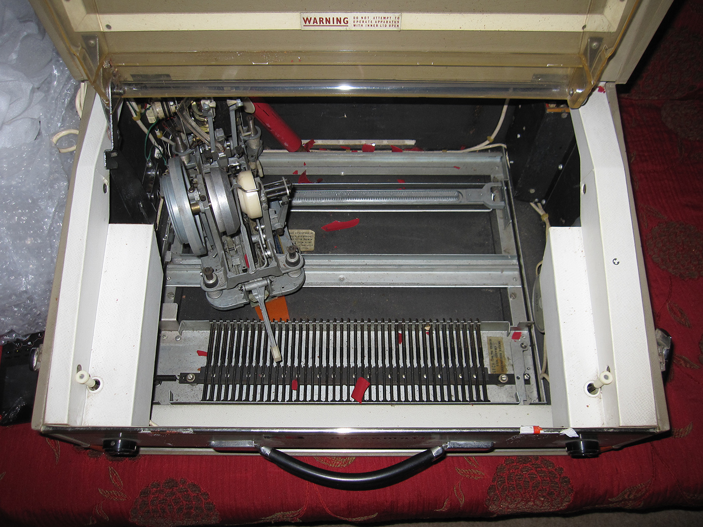
The outer, wooden lid is fixed to the case on a KB Discomatic. When lifted, the outer lid will lock in a vertical position. When the outer lid is open, the inner dustcover lifts upward and outward slightly. This can be seen in the first photo below.
The inner lid can then be lifted to enable record changing etc. The inner lid balances vertically (and a bit precariously!) when open. This is shown in the second photo.

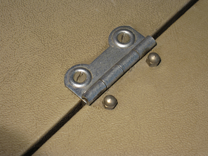
Outer lid hinges
The outer lid hinges are made from thin metal plate. They will work just fine if the machine is handled carefully but can easily be distorted if the lid is forced.
The fixings shown in the photo are original, both for the exterior and interior. These are 6BA x 1/2" screws with dome nuts. They are often corroded so stainless steel replacements are a good idea.
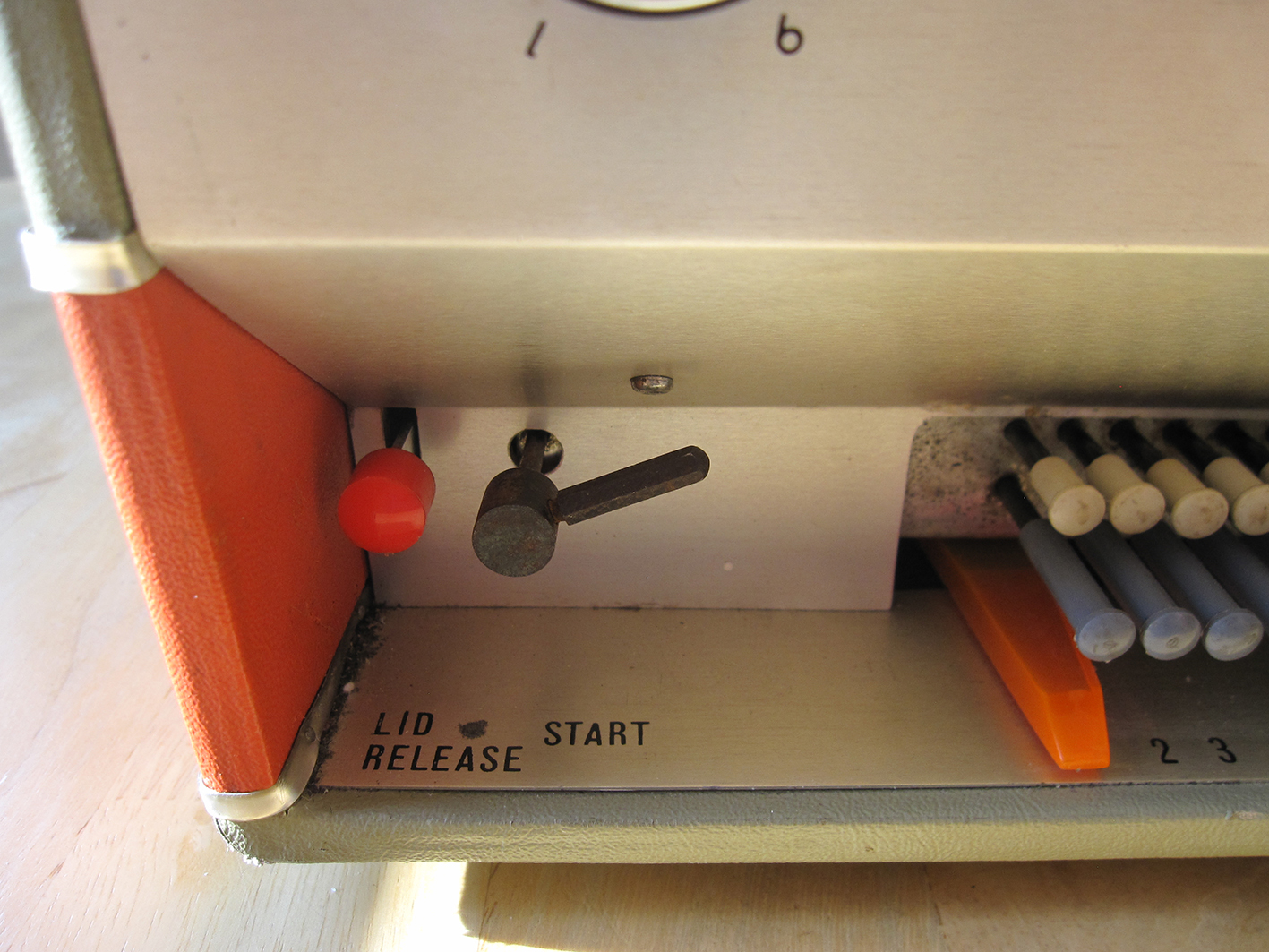
Outer lid release
Before closing the outer lid it is necessary to press in the Lid Release button on the front panel to release the latch. There is a mechanical interlock that prevents the Lid Release button being pressed unless the mechanism is stationary in the 'home' position.
Many KB Discomatics have damage to the outer lid hinges and inner lids caused by misoperation of the lid mechanism. It's not immediately obvious that the Lid Release button should be pressed before closing the outer lid and many machines have lids that have been forced.
This must have become a problem for KB and I have seen the warning label shown below on the lid of some KB Discomatics with very late serial numbers.

Inner lid power interlock
The lids include a mains power interlock.
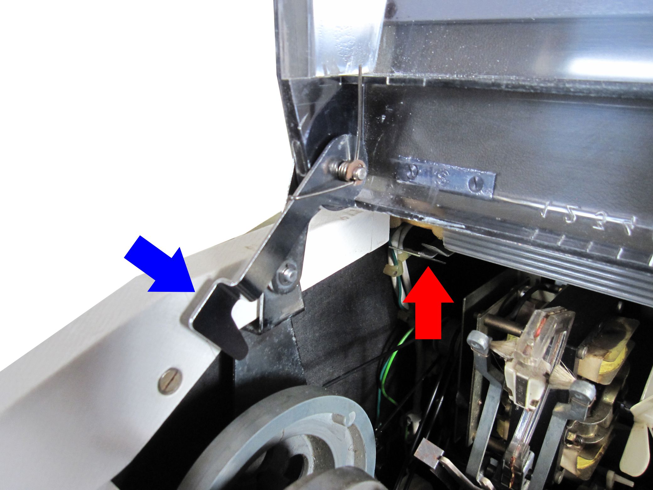
This comprises two microswitches with long levers fixed into the top left corner of the case. These are operated by a lever linked to the inner lid. Live and neutral mains input wiring each pass through one of the microswitches.
When the outer lid is closed or when the inner lid is opened (for example, when changing records) a lever attached to the inner lid releases the microswitches and the the power is cut. When playing records the outer lid must be open and the inner lid must be closed for the power to switch on.
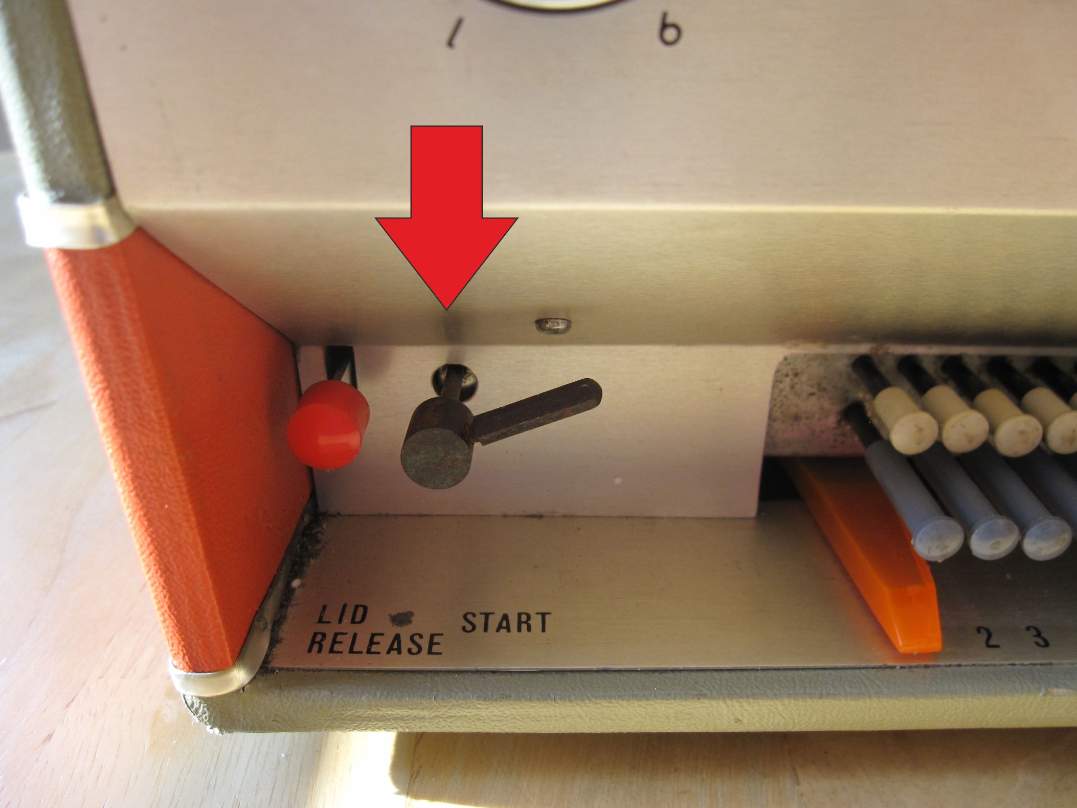
The first photo shows the lever (arrowed blue) and the location of the switches (arrowed red).
The second photo shows the microswitches removed from the case. Here you can see that the microswitches are contained within a housing that prevents accidental contact with the terminals.
The operating levers of the microswitches will often be distorted. In this case power will not switch on when the lid is closed. Once distorted, the levers can never be successfully straightened while the switches are installed in the cabinet. They should be removed, dismantled, levers straightened and re-assembled.
location of lid switches
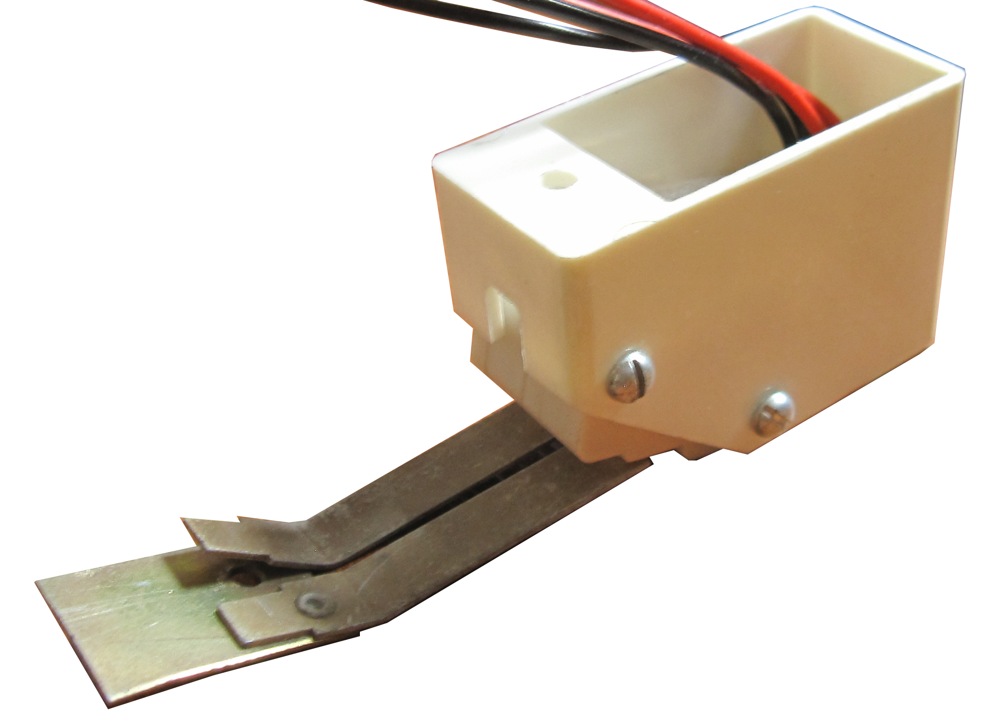
housing removed from the case
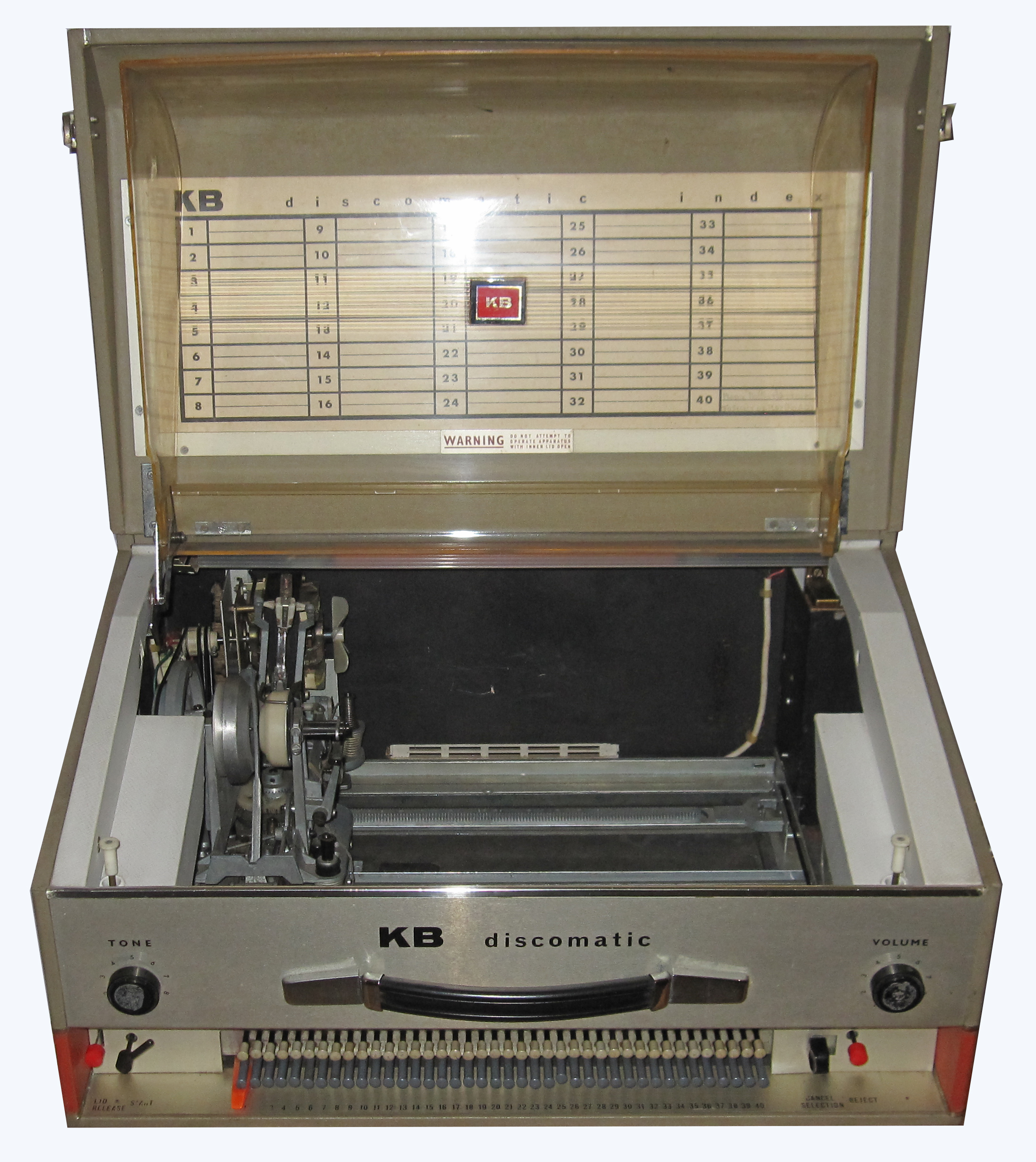
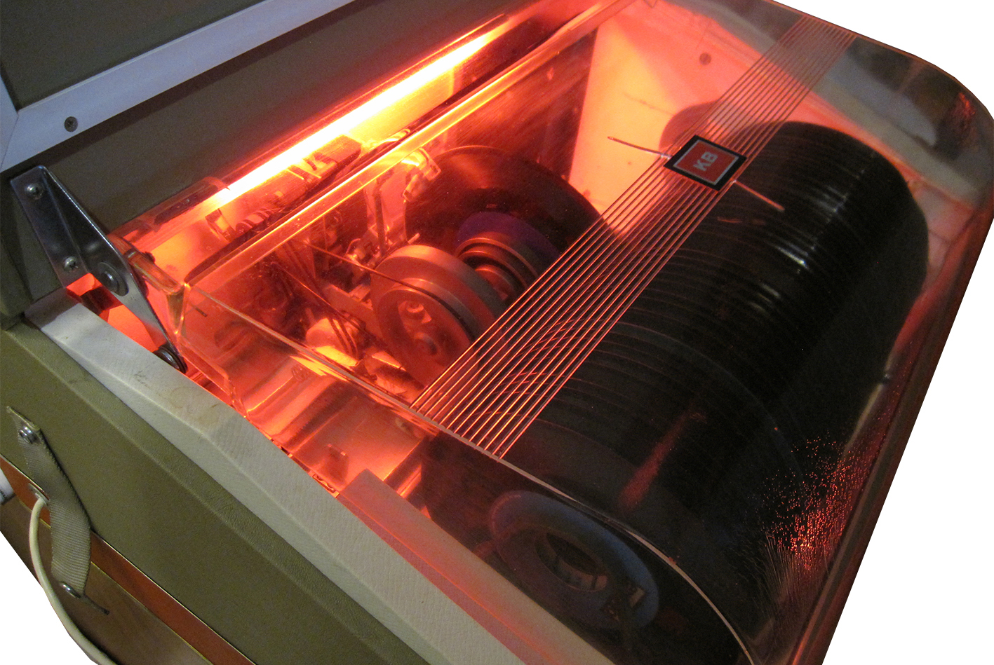
KB Discomatic interior and illumination
The interior of the KB Discomatic is illuminated by a red coloured filament striplight when playing. The interior of most KB Discomatics is painted black, but I have seen two examples that were painted white. The white finish is rather nice, particularly when the striplight is on.
KB Discomatic controls
The KB Discomatic has front panel controls for Volume and Tone. Operational controls are located along the bottom of the front panel as follows:
- Lid release. Press to unlock the outer lid and allow it to be closed. The inner dustcover must be closed before closing the outer lid.
- Start lever. Twist to start the player searching for a selection. The Start lever will remain locked downward until the player has completed the scan. When the scan is completed the Start lever will return to the upward position.
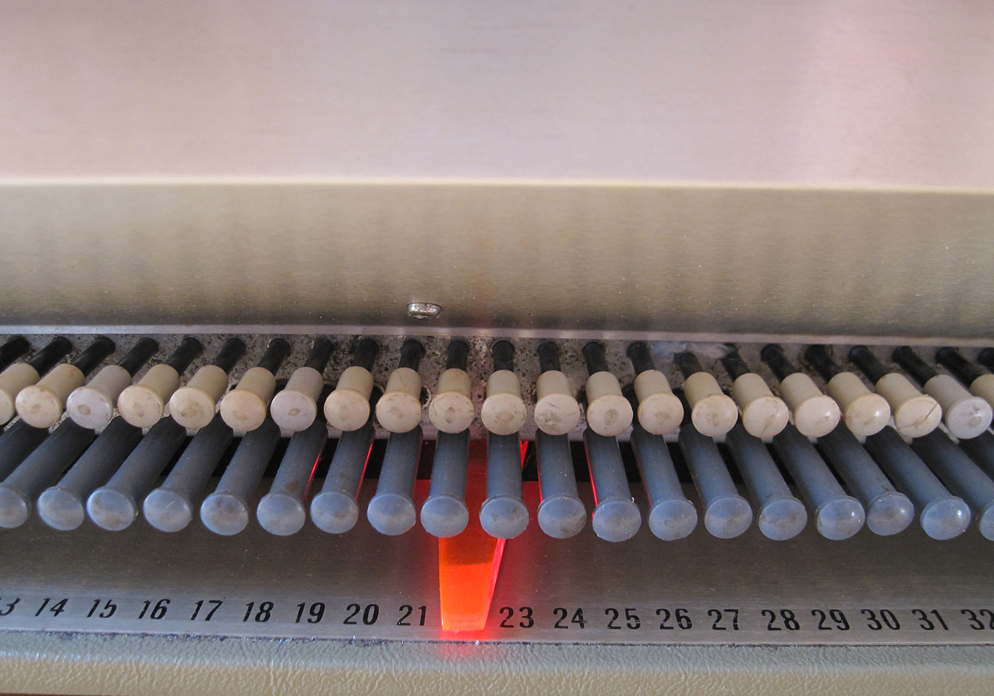
- Selection buttons. In common with all Discomatics, A or B sides of each record can be selected by pressing any of the 80 selection buttons. Any number of sides can be selected simultaneously. When a record is selected to play the button pops out.
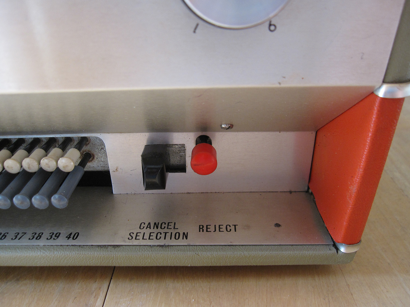
- Cancel selection. Move this slider to the right to cancel all selected buttons.
- Reject. Pressing this button will reject the record side currently playing and move to the next selection (if any).
and start lever
and reject button
KB Discomatic Now Playing indicator
An orange/pink coloured acrylic pointer attached to the front of the mechanism moves above the selection numbers to indicate the selection now playing. The pointer is illuminated by a miniature lamp, powered from the power supply in the amplifier. When the amplifier is running the pointer will light.
The pointer is a great feature and when properly set up glides magically up and down as the mechanism scans. Unfortunately,sixties engineering wasn't always that precise and I have seen a few machines where both the pointer and buttons are mis-aligned with the number scale on the cabinet.
KB Discomatic mechanism
The KB Discomatic includes a first-generation Discomatic mechanism. This is identified primarily by the twist-start control at the left of the front panel.
These early mechanisms also featured in the Gerinvex Type A Discomatics, early Victor consoles and I believe early examples of TD-ASS and TD-COF.
KB Discomatic amplifier
The amplifier is an early all-PNP transistor design. It has a common emitter gain stage coupling to a single-ended transformer driver. The dual secondaries of the driver transformer drive the output pair which have preset alignments to set their operating point. The output pair are indirectly coupled to the 25 ohm speaker load. The amplifier is powered from a single rail of approximately -24V.
The amplifier sounds fine when working correctly but will never break any performance records!
According to my measurements it will typically achieve almost 1.5W output power (for 5% THD). Distortion at 0.5W is around 3%. Signal/Noise ratio approximately -62dB ref full power.
For such a simple circuit the amplifiers can be challenging to service as there are many common faults.
The amplifier is housed with its transformer in a metal chassis located in the back, right corner of the cabinet. An 82R 5W resistor is also mounted on the chassis. This is wired in-line with the AC voltage from the power transformer and feeds the pointer lamp on the mechanism.
The mains feed for the amplifier is wired in parallel with the motor and striplight so will only switch on when the mechanism is running.
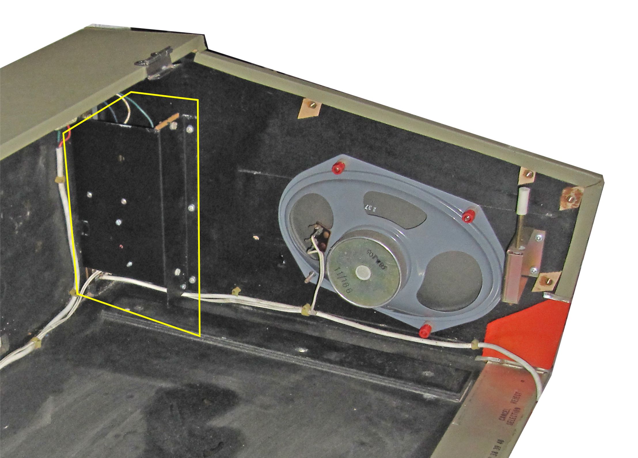
The first photo shows the location of the amplifier chassis (yellow boxed) at the back corner of the cabinet. The mechanism chassis has been removed for clarity.
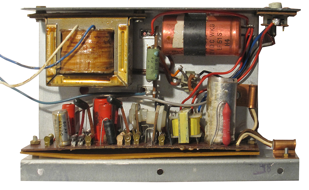
The second photo shows the contents of the amplifier chassis. The amplifier shown is an unrestored example. Connections for the input from the volume control are made to the EXT'N AMPL socket at the top right. Connections to the speaker are made to the switched contacts of the EXT'N L/S socket in the same area.
KB Discomatic output connections
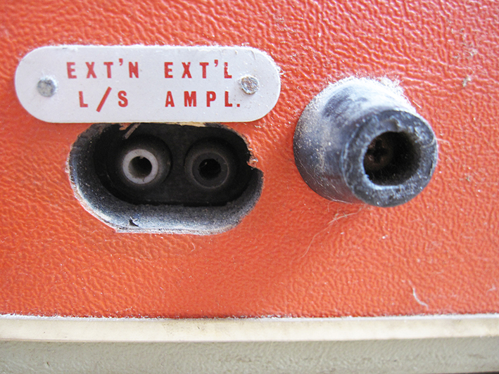
The KB Discomatic features speaker and line output connections. These are both located at the left end of the back panel (viewed from the back), labelled 'EXT'N L/S' (speaker) and 'EXT'L AMPL' (line). The connections are both made via RCA phono jacks. When connection is made to the speaker output the sound from the internal speaker is muted.
The speaker output should only be connected to speakers with an impedance greater than 22 ohms. The amplifier may be damaged by lower impedances.
The line output connection is mono and can be connected to an amplifier with impedance and sensitivity to match a ceramic cartridge, That is a sensitivity of approximately 1V and input impedance greater than 500 kOhm. The input should be unequalised (not RIAA equalised for moving magnet or moving coil cartridges).
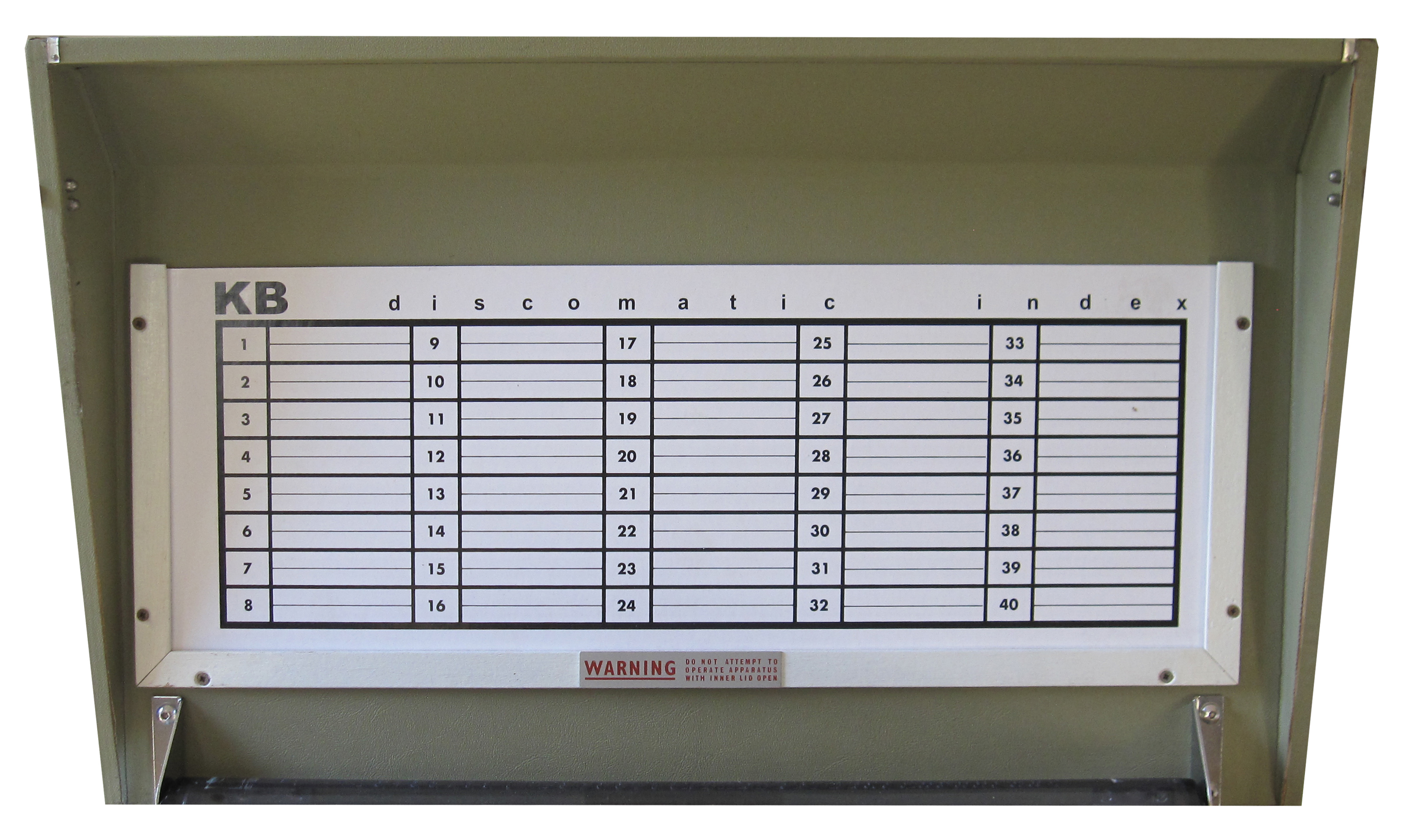
KB Discomatic title cards
The KB Discomatic featured a frame fixed to the inside of the outer lid to hold a title card. This arrangement was unique to the KB. It was quite a cool feature, displaying the record titles when the outer lid was open.
The title card was made of thin cardboard and was double-sided. It included 80 spaces for the KB owner to write the titles of the record selection they had loaded.
I can imagine that in the sixties the proud KB owner would have purchased spare record racks and title cards to enable them to swap their selections quickly and easily.
It's simple enough to draft up a paper replacement for the original title card, but I do generally stock full-size card replicas if you want a more original look. The replicas are printed double-sided on the correct gauge of card using re-generated artwork. Contact me if you are interested in buying title cards for your KB.
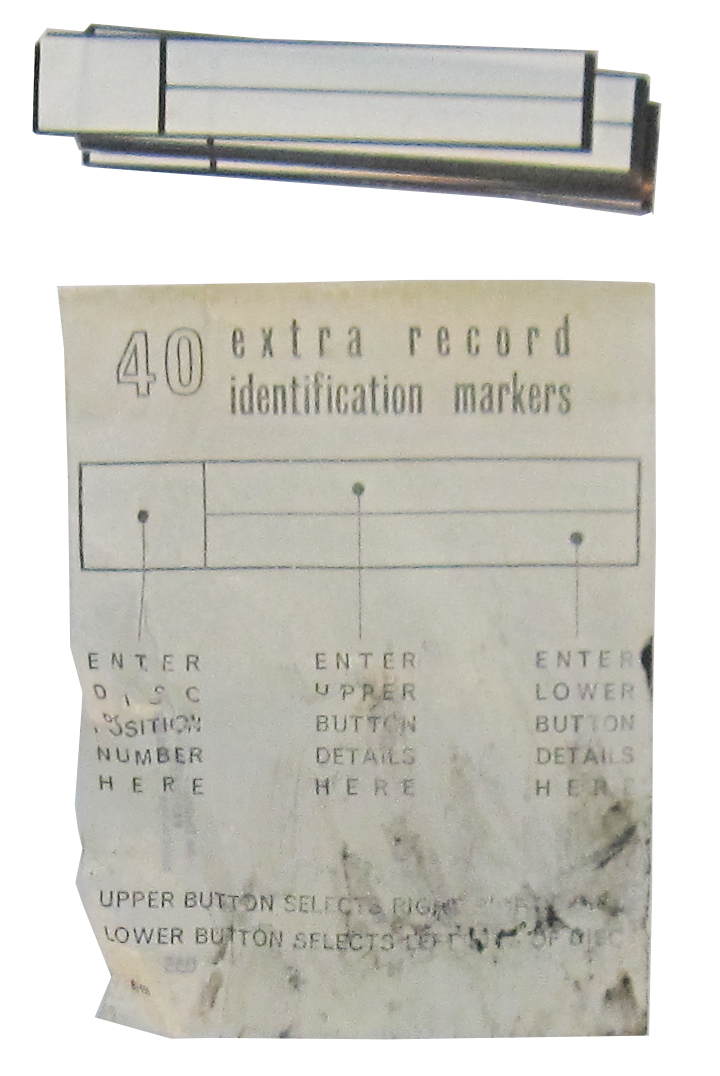
KB Discomatic title card stickers
Stickers were also available to cover the entries if records were changed and a complete new card was not necessary. The stickers were self-adhesive and could be stuck over entries on the title card to keep the title card in step with any record changes.
These are very rarely seen now, but I do have one set in the original packet. There's a photo here of them with the packet pictured below.
From the left the instructions on the packet read
ENTER DISC NUMBER HERE
ENTER UPPER BUTTON DETAILS HERE
ENTER LOWER BUTTON DETAILS HERE
At the bottom of the packet there's a note to remind the user
UPPER BUTTON SELECTS RIGHT SIDE OF DISC and
LOWER BUTTON SELECTS LEFT SIDE OF DISC
KB Discomatic shipping clamp
When new, the KB Discomatic was supplied with a two-part shipping clamp. The transit clamp secured the right side of the mechanism to the base to ensure that the heavy mechanism could not lift off the track and come loose inside the case.
One half of the clamp is a bracket fixed to the base of the cabinet by three screws. This part will be present in most KB machines. The other half of the clamp is a removable L-bracket that fixes to the base bracket with a single screw. The L-bracket has often been mislaid as owners would remove it after delivery and discard it. It's possible they didn't realise that the L-bracket could be reversed and fixed to the base bracket for storage until future use.
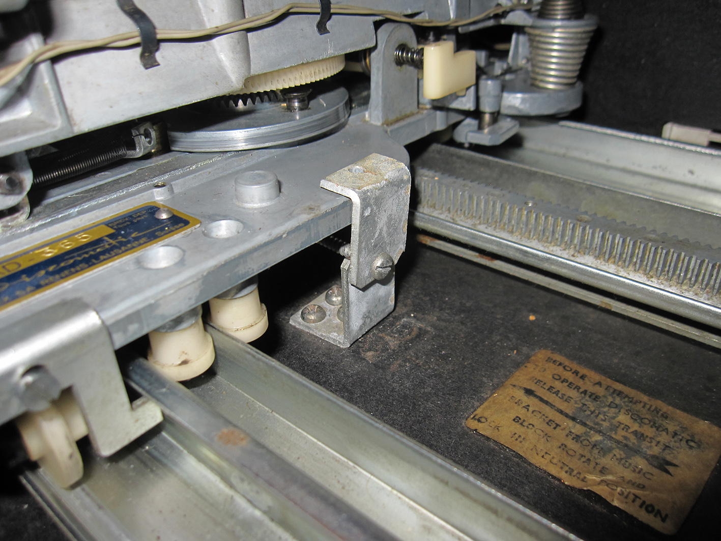
The first photo shows the shipping clamp stored during use. The second photo shows the shipping clamp reversed and fixed in its shipping position.
I would never attempt to ship a KB Discomatic without a transit clamp fitted. The third photo shows a nice, one owner KB Discomatic that was damaged when the mechanism came loose during shipping. The tonearm was broken in several places, the dustcover damaged, the striplight smashed and some of the mechanism was damaged. Fortunately, the machine was restorable.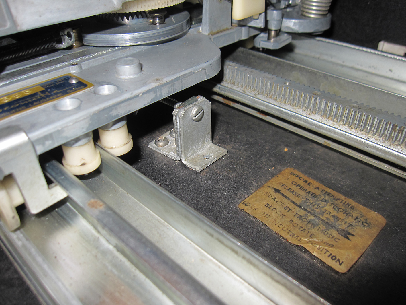
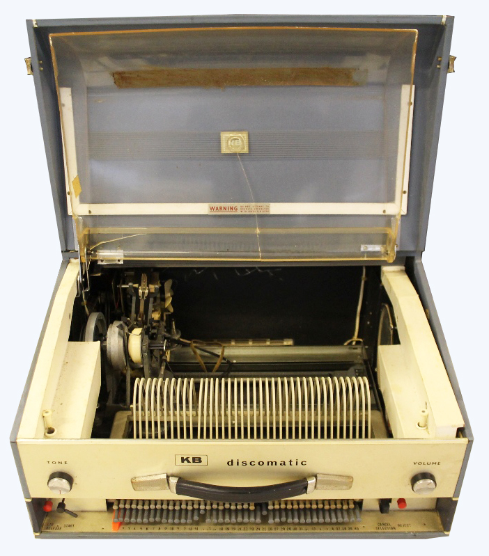
KB Discomatic variants
The KB design was quite stable and changed little through the years it was manufactured. The most obvious change was when a two-tone blue version was introduced towards the end of the players' life as an alternative to the beige/orange finish.
Internally there were a few subtle changes over the years which are worth noting.
Motor changes for the KB Discomatic
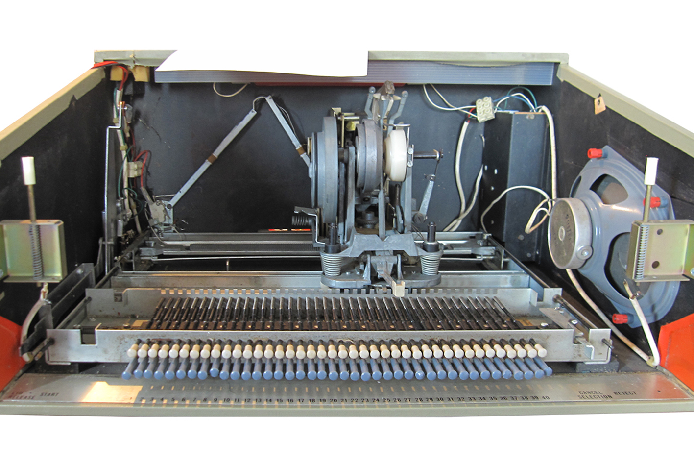
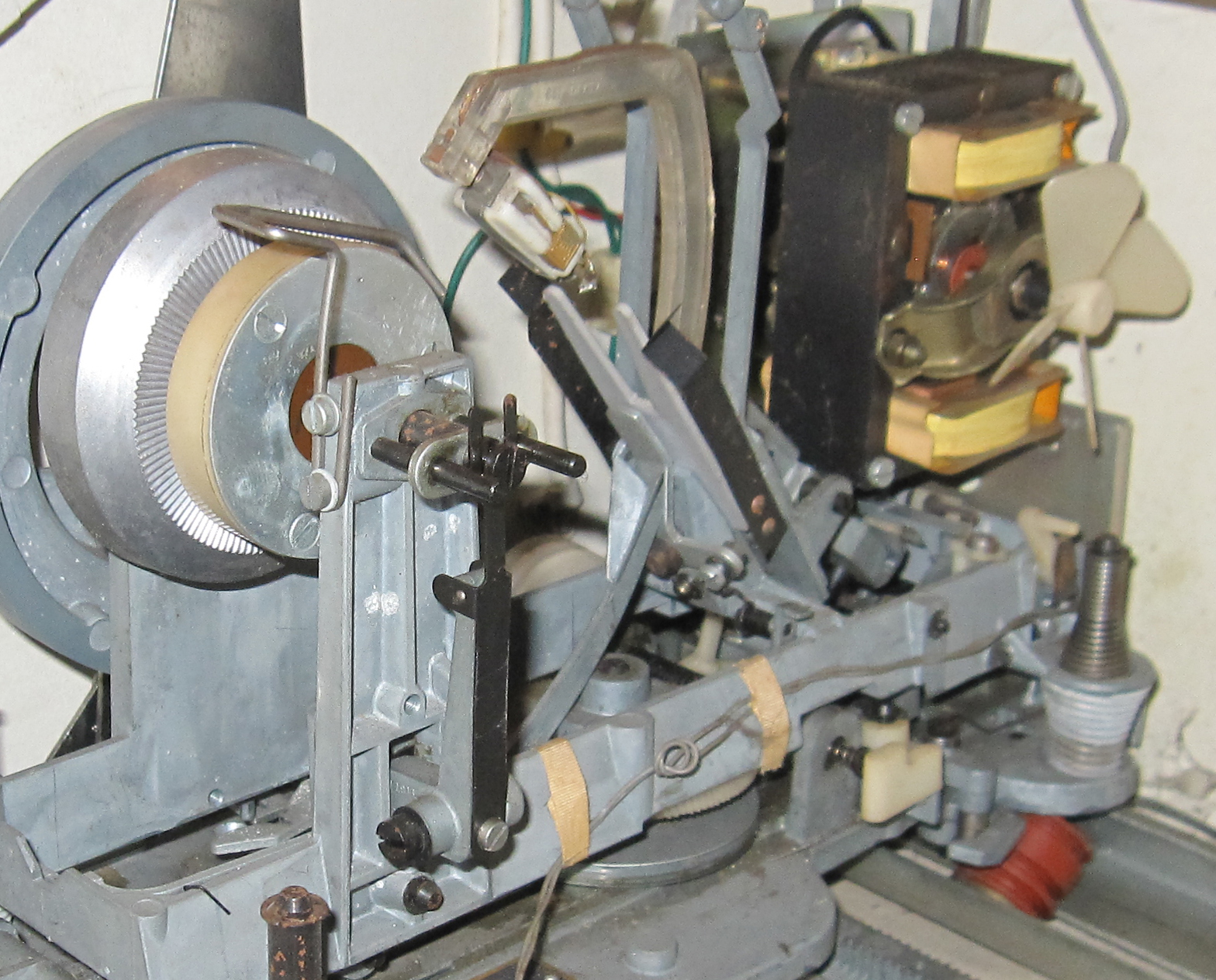
Cylindrical motor
The KB was originally fitted with a black, cylindrical motor which was soon updated to a rectangular motor. Refer to photos to see both motor types. In my experience the cylindrical motor has lower torque than the rectangular motor and can have problems starting the carriage from rest. This could have been the reason for the motor change.
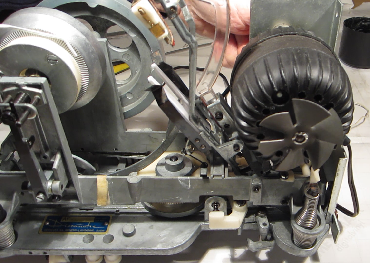
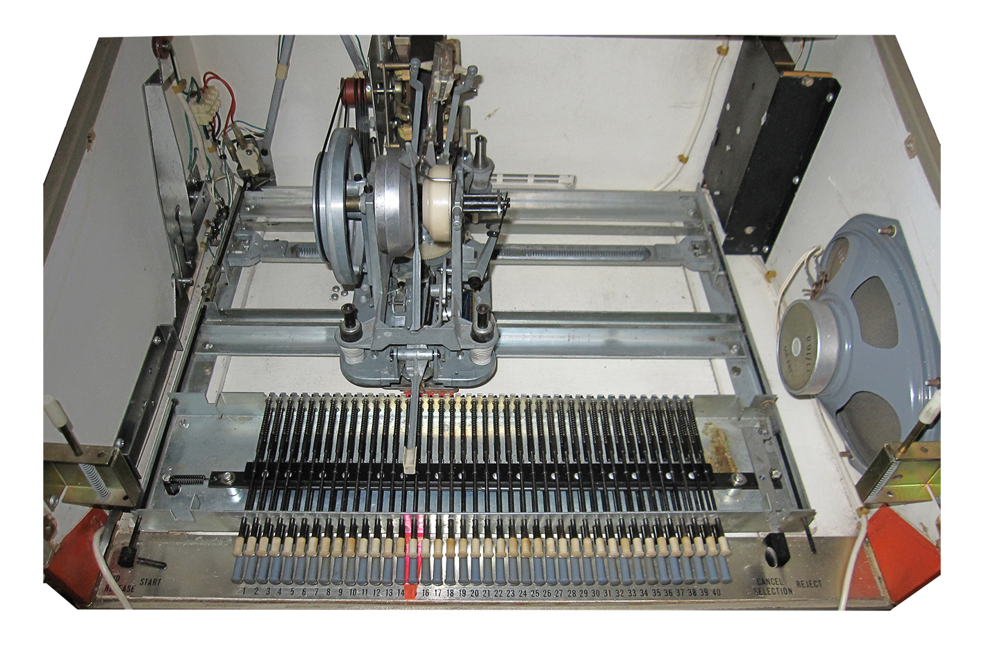
Rectangular motor
The cylindrical motor was discontinued at quite an early stage of production and replaced by a rectangular motor. This motor continued for the remaining life of the KB Discomatic.
Note that both motor types used in the KB Discomatic operate from 220-240V.
Cabinet wiring changes
The cabinet wiring changed slightly which caused a few consequential changes. Original KB models had a tag strip fixed to the back left of the chassis (boxed red in the photo). This is used as a junction between the wiring from the mechanism and the wiring from the cabinet and is quite difficult to wire neatly. The tagstrip was removed for later units (earliest I have recorded of the new style is 952/04783) and much of the wiring changes accordingly.
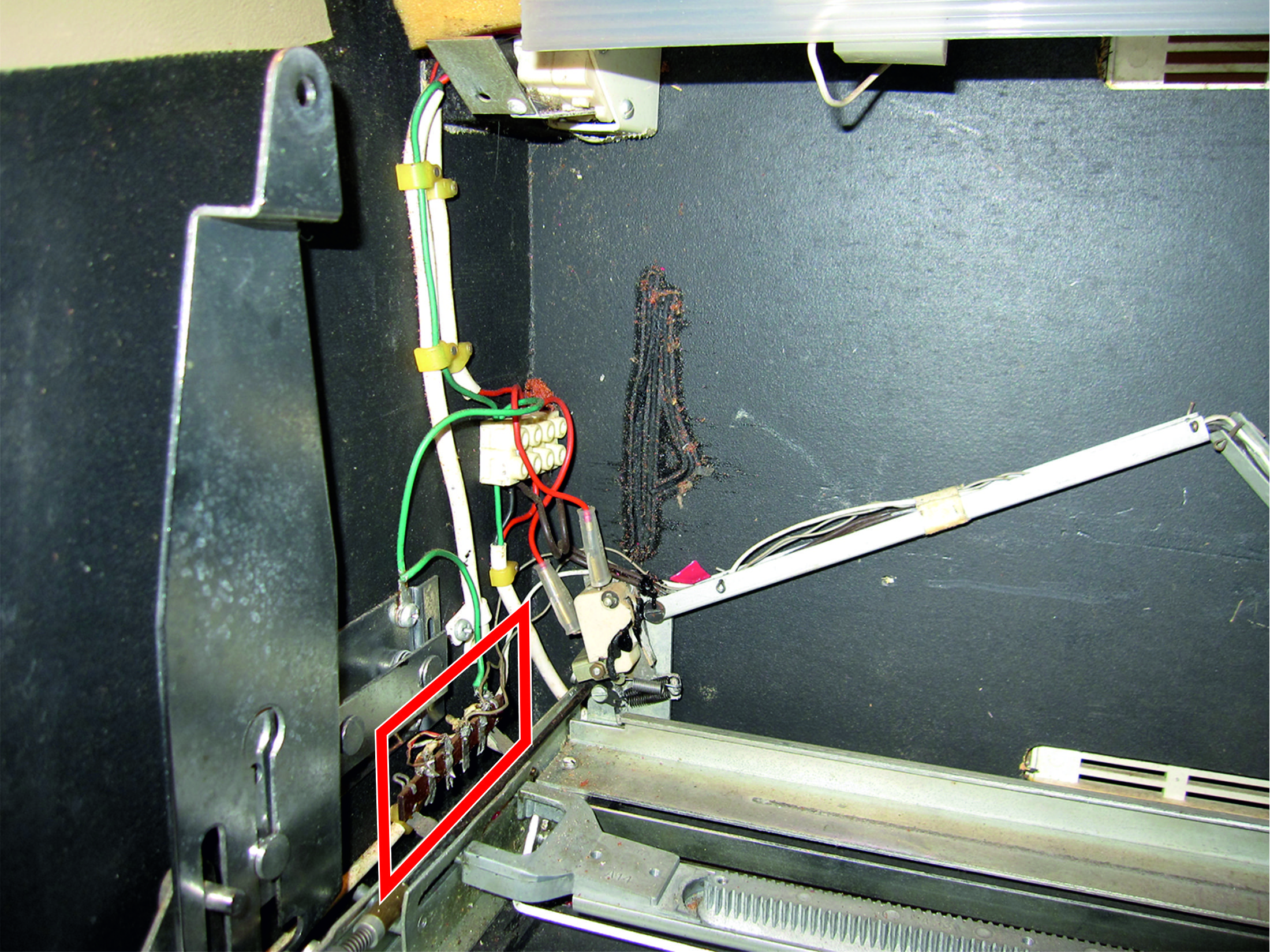
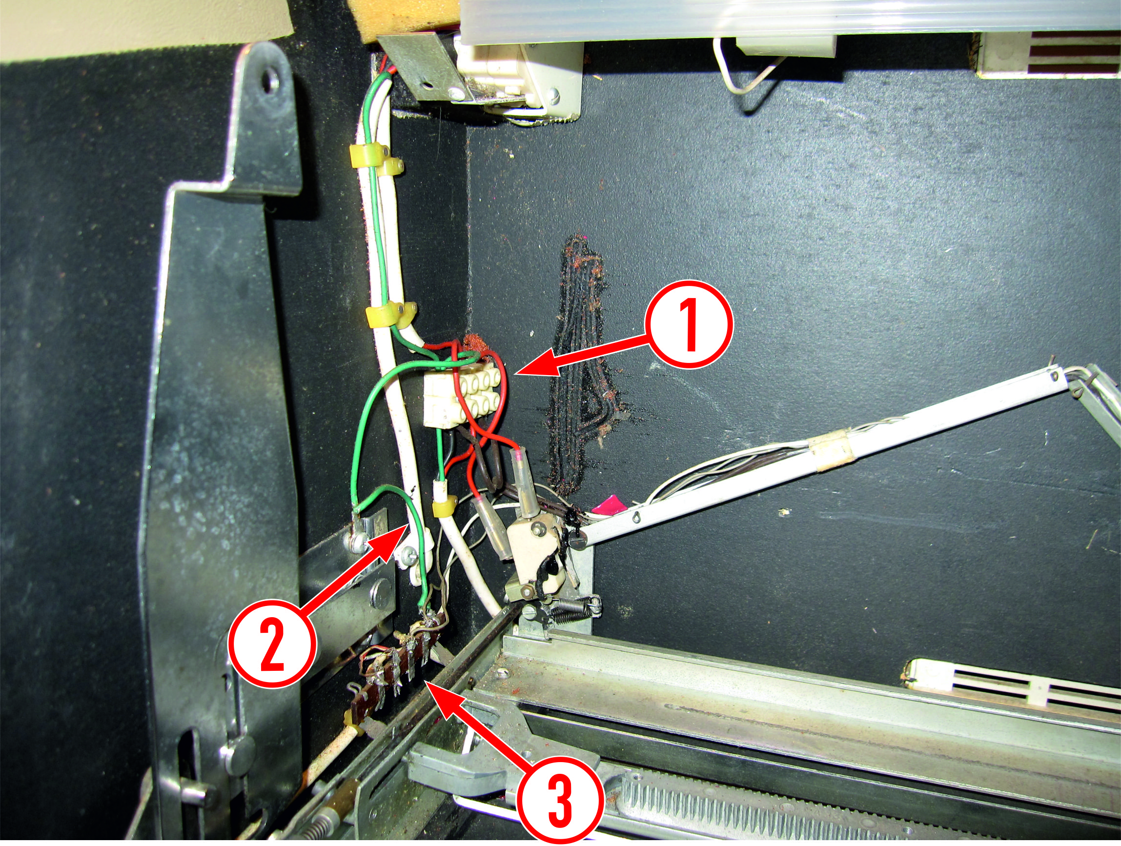
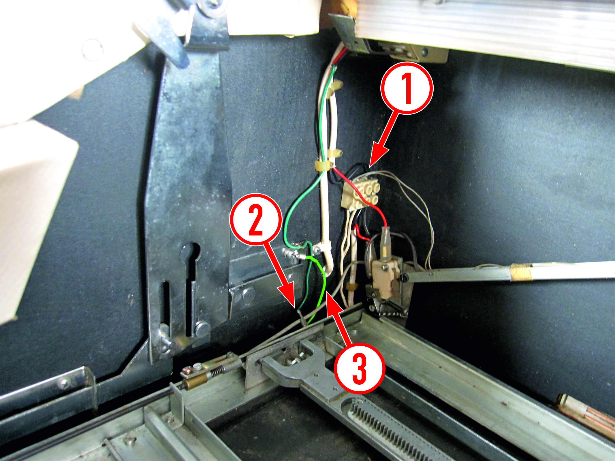
Early wiring with tag strip
The photos below show the early wiring arrangements for machines with a tag strip fixed to the mechanism.
- 4 way connector block for mains ground, neutral, live and switched live to feed the motor, amplifier and striplight.
- Mechanism chassis grounded via a wire soldered to the tagstrip.
- Tagstrip fixed to the mechanism.
- 3 way connector block for power feed to the strip light and amplifier, also amplifier ground.
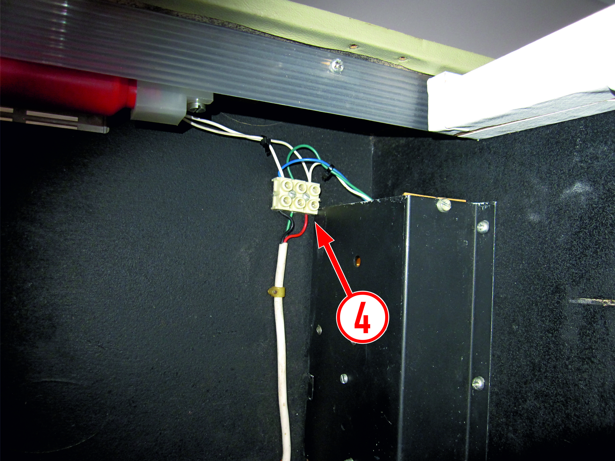
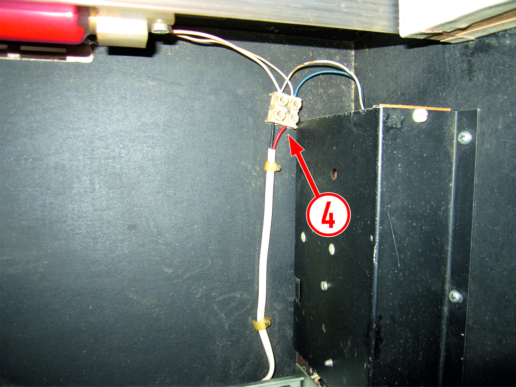
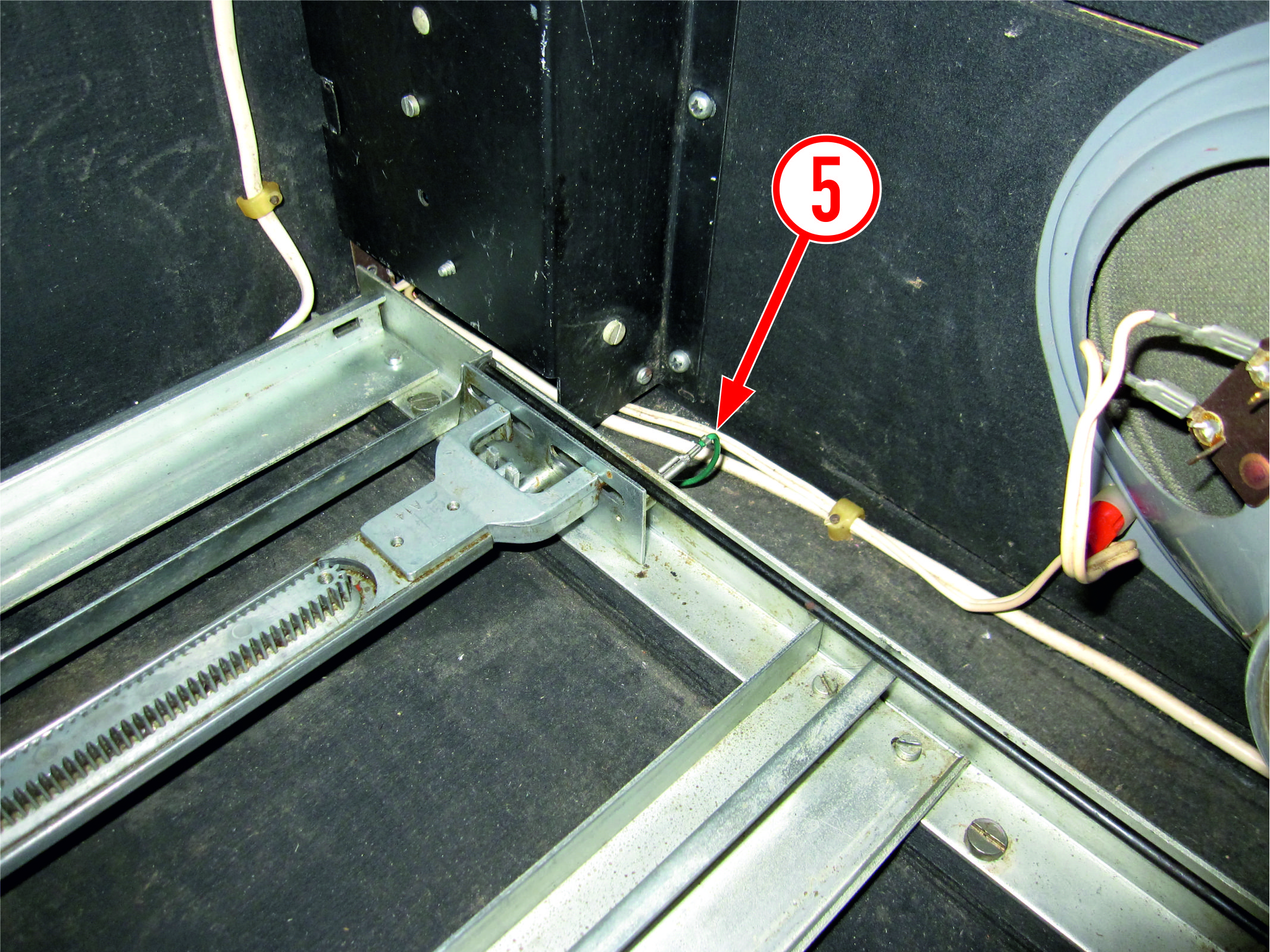
Later wiring without tag strip
The photos below show the later wiring arrangements for machines that don't have a tag strip fixed to the mechanism.
- 3 way connector block for the wiring from the pointer lamp and mains neutral.
- Mechanism chassis grounded via detachable 2.8mm tag.
- In this example the green wire is non-original, running a secure ground from the front panel to mains ground.
- 2 way connector block for power feed to the strip light and amplifier.
- Separate ground connection from the amplifier to the mechanism chassis via detachable 2.8mm tag.
Sitemap
Parts sales
For parts and accessory sales, Discomatic UK is a trading subsidiary of Ask Stuart Ltd.
Copyright
Site content copyright © Ask Stuart Ltd. 2018